How to match pipe and regulator specifications in chemical processing lines
Why pipe and regulator specifications should be selected together
A pipe and regulator combination does more than control pressure. In chemical processing lines, it affects flow stability, leakage risk, corrosion resistance, maintenance access and whether overpressure protection can work as intended. A regulator that looks correct on its nameplate can still perform poorly if upstream pipe losses are high, downstream volume is too small, fittings create turbulence, or materials are incompatible with the fluid. Strong piping also cannot make a poorly selected regulator safe.
The practical approach is to define the operating envelope first: inlet pressure range, required outlet pressure, minimum and maximum flow, fluid phase, temperature, material compatibility, failure modes and applicable code basis. Engineers can then select the pipe schedule, connection type, regulator style, relief device and inspection plan as a matched system.
What a pressure regulator can and cannot do
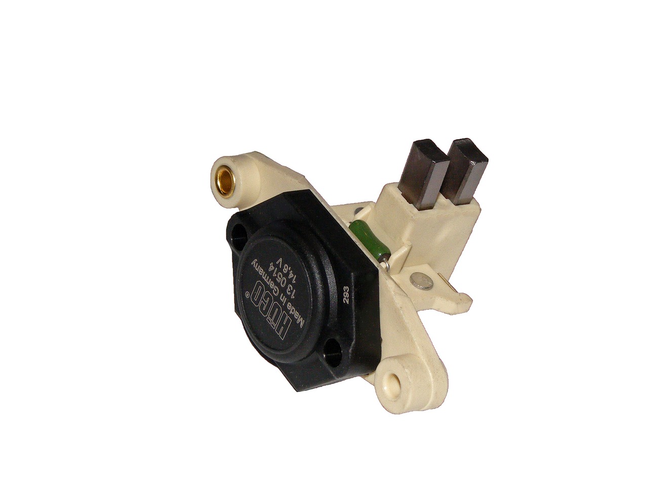
A pressure regulator is a control device. It adjusts an internal valve element to maintain a target downstream or upstream pressure within its performance limits. It is not automatically a safety relief device, a shutoff valve, a check valve or a substitute for a properly engineered overpressure protection system.
In process service, the two most common categories are pressure-reducing regulators and back-pressure regulators. A pressure-reducing regulator lowers a higher inlet pressure to a controlled downstream pressure. A back-pressure regulator holds pressure upstream by opening when upstream pressure rises above its set point. Both are used in chemical dosing, gas distribution, analyzer systems, pilot lines, tank blanketing and utility services, but they respond differently to flow changes.
Pressure-reducing regulation
Pressure-reducing regulators are often installed where a plant air header, nitrogen header, gas cylinder, pump discharge or high-pressure supply must feed equipment at a lower pressure. Selection should consider maximum inlet pressure, desired outlet range, flow curve, droop, seat material, body material and lock-up behavior. Droop means the outlet pressure falls as flow increases. Lock-up describes the pressure rise above set point when flow stops.
Back-pressure regulation
Back-pressure regulators are used to maintain upstream pressure, stabilize pump discharge, protect analytical systems, or keep liquid systems above vapor pressure. They should not be treated as general-purpose relief valves unless the device is specifically rated and applied for that safety function. If loss of regulation can create pressure above the rating of the weakest downstream component, a separate relief or limiting device may be required.
How pipe conditions affect regulator performance
Regulator behavior is strongly influenced by the piping around it. A regulator senses and reacts to pressure, but the pressure at the sensing point may not be the same as the pressure at the equipment being protected or supplied. Long runs, undersized pipe, restrictive fittings, strainers, heat exchangers, check valves and partially open isolation valves can all increase pressure drop.
For gases, pressure drop can also change density and velocity. For liquids, high velocity can increase noise, erosion and water hammer risk. For two-phase or flashing service, many standard regulator assumptions may no longer apply. These issues are why a pipe and regulator package should be reviewed against flow data, not nominal pipe size alone.
- Upstream pressure losses can starve the regulator and make outlet pressure unstable at high demand.
- Downstream restrictions can hide true equipment pressure and create unexpected pressure accumulation.
- Small downstream volume can cause cycling, chatter or rapid pressure swings in fast on-off service.
- Poor sensing line location can make the regulator control the wrong point in the system.
- Dirty piping can damage seats and diaphragms, especially during startup after fabrication.
Selection inputs to define before buying components
Before comparing catalogs, define the service conditions in writing. This is especially important for chemical equipment because the same nominal regulator size can behave very differently in nitrogen, steam, solvent vapor, acid feed, caustic solution or viscous liquid service.
| Input | Why it matters | Common mistake |
|---|---|---|
| Minimum and maximum inlet pressure | Determines regulator spring range, body rating and supply pressure effect | Selecting only for normal pressure and ignoring startup or cylinder pressure |
| Required outlet or upstream set pressure | Defines the controlled pressure range | Choosing a spring range where the normal set point sits at the extreme end |
| Minimum, normal and peak flow | Needed to read flow curves and estimate droop | Sizing from pipe diameter instead of actual demand |
| Fluid identity and phase | Controls material compatibility, sealing method and venting practice | Using air-service components for corrosive or hazardous chemicals |
| Temperature range | Affects elastomers, polymers, pressure rating and condensation risk | Checking only room-temperature ratings |
| Failure consequence | Determines whether independent relief, limiting or shutdown protection is needed | Assuming the regulator alone protects downstream equipment |
| Maintenance access | Affects isolation, bypass, drain, vent and inspection layout | Installing the regulator where gauges and nameplates cannot be read |
For additional component topics in this equipment category, see the Pumps and Valves section.
Standards and safety references that influence design
Chemical process piping is commonly designed with reference to ASME B31.3, which covers process piping in chemical, petroleum, pharmaceutical, semiconductor, cryogenic and related process plants. The standard addresses design, materials, fabrication, assembly, erection, examination, inspection and testing. It does not remove the need to verify regulator supplier data, the process hazard analysis, or local legal requirements.
Where OSHA process safety management applies in the United States, 29 CFR 1910.119 requires process safety information and mechanical integrity practices for covered highly hazardous chemical processes. In that context, process piping, piping components, relief and vent systems, pumps, controls and safety systems may all fall within the mechanical integrity program. For gas welding and cutting work, OSHA rules also emphasize suitable regulators, proper working condition of regulators and gauges, and safe handling of oxygen and fuel gas equipment.
Gas pipeline rules provide another useful lesson, even when they do not directly govern an internal plant process line. PHMSA rules in 49 CFR Part 192 require protection against accidental overpressuring in regulated gas pipeline systems when pressure control failure could exceed maximum allowable operating pressure. The transferable design principle is simple: pressure reduction and overpressure protection should be considered separately. See also: Storage Systems.
| Reference area | Relevant design lesson | How to apply it cautiously |
|---|---|---|
| ASME B31.3 process piping | Piping components need a defined pressure, temperature, material and examination basis | Use it as a process piping framework, not as a regulator performance curve |
| OSHA PSM mechanical integrity | Covered sites must maintain integrity of process equipment and safety systems | Include regulators, relief devices and associated piping in inspection planning when they are safety-relevant |
| Compressed gas and hot-work rules | Regulators and gauges must be suitable and in proper condition for gas service | Do not interchange gas regulators or connections casually |
| Gas pipeline overpressure rules | Failure of pressure control can require independent pressure relief or limiting protection | Use the concept, while confirming which regulations apply to the actual installation |
Installation details that often decide success or failure
Many regulator problems start with installation. A well-selected device can fail early or control poorly if pipe stress is transferred into its body, debris reaches the seat, or operators cannot vent trapped pressure before maintenance.
- Install strainers or filters when required. Seat damage from weld scale, sealant, corrosion products or catalyst fines can cause creeping outlet pressure.
- Support the pipe, not the regulator. Small regulators should not carry the load of unsupported pipework, vibration or misaligned threaded connections.
- Provide readable gauges. Upstream and downstream pressure indication helps operators distinguish supply problems from regulator problems.
- Avoid unsafe trapped volumes. Isolation valves should be arranged with venting or draining where trapped hazardous pressure could remain during maintenance.
- Check flow direction. Reverse installation can damage internals or produce uncontrolled pressure behavior.
- Plan for relief discharge. If a relief valve or vent is used, the discharge destination must be compatible with the chemical, pressure, temperature and environmental limits.
Thread sealants and gaskets also need attention. Excess sealant can enter the regulator. In oxygen service, oil, grease and incompatible materials can create severe hazards. In corrosive service, the wetted path should be reviewed part by part, including body, seat, diaphragm, O-rings, springs, fittings and sensing lines.
Maintenance and troubleshooting signals
A regulator should be inspected as part of the system, not only as a standalone component. Changes in downstream pressure may originate from plugged upstream filters, changed demand, blocked vents, damaged sensing lines, worn seats, incorrect spring range or a relief device that is lifting too close to normal operating pressure.
- Outlet pressure rises when demand stops. Possible causes include seat wear, contamination, wrong elastomer, thermal expansion or damaged internals.
- Outlet pressure falls at peak demand. Possible causes include undersized regulator, excessive pipe pressure drop, plugged inlet filter or supply pressure below design assumptions.
- Pressure oscillates. Possible causes include oversizing, low downstream volume, fast-cycling valves, poor sensing location or two-phase flow.
- External leakage appears. Possible causes include diaphragm failure, seal attack, loose fittings, pipe strain or temperature cycling.
- Relief devices operate frequently. Possible causes include incorrect set points, regulator creep, blocked downstream flow, thermal expansion or process changes not reflected in the design basis.
Maintenance intervals should reflect service severity. Clean, dry inert gas service may allow longer intervals than corrosive gas, slurry, wet steam, polymerizing fluid or toxic chemical service. After any chemical service change, the regulator and nearby piping should be reviewed for material compatibility and pressure rating before restart.
A practical pipe and regulator specification checklist
For many facilities, the most useful deliverable is a short specification sheet that prevents hidden assumptions. The sheet should travel with the purchase request, installation package and maintenance file.
- Define the fluid name, concentration, phase, impurities and expected upset conditions.
- Record minimum, normal and maximum inlet pressure at the regulator inlet, not only at the source.
- Record required controlled pressure at the actual point of use or protection.
- List minimum, normal, peak and no-flow conditions.
- Confirm pipe code basis, design pressure, design temperature, corrosion allowance and test requirements.
- Check regulator body, trim, seat, diaphragm and seal compatibility with the chemical and temperature range.
- Review flow curves for droop, choked flow and lock-up behavior.
- Verify whether independent relief, limiting, alarm or shutdown protection is required.
- Specify gauges, vents, drains, filters, isolation valves and support requirements.
- Document inspection, cleaning, calibration and replacement intervals.
The practical takeaway is that regulator selection should not be reduced to nominal pipe size and set pressure. The safer question is whether the installed system can control pressure across the full operating envelope and fail in a way that the piping and downstream equipment can tolerate.
Frequently asked questions
Can a regulator replace a relief valve?
Usually no. A regulator controls pressure during normal operation, while a relief or pressure-limiting device is intended to address defined overpressure scenarios. Some devices have relieving features, but that does not automatically make them suitable as code-required overpressure protection.
Should the regulator size match the pipe size?
Not necessarily. Regulator size should be based on flow, pressure drop, fluid properties and control range. A regulator with the same nominal connection as the pipe can be oversized or undersized depending on demand and pressure conditions.
Why does downstream pressure drop when flow increases?
This is often droop. It can be caused by regulator characteristics, low inlet pressure, excessive upstream pipe loss, undersized components, plugged filters or flow demand beyond the selected range.
What should be checked before using a regulator with a different chemical?
Check all wetted materials, seals, elastomers, lubricant restrictions, pressure rating, temperature range, cleaning requirements and venting arrangements. A regulator that is acceptable for inert gas may be unsafe for oxygen, corrosive gas, solvent vapor or reactive chemical service.