Circulating pump isolation valves for maintenance, safety and flow reliability
Why isolation valves matter in circulating pump loops
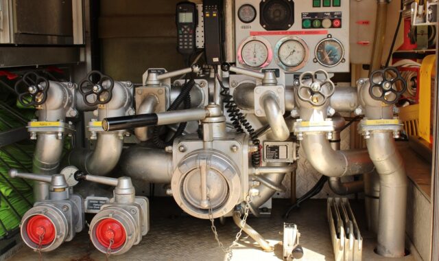
Circulating pump isolation valves are the block valves installed around a pump so the pump, strainer, check valve, instruments or a short pipe section can be taken out of service without draining or shutting down more of the system than necessary. In chemical plants, utility skids, heat transfer loops and water treatment systems, these valves are more than convenient accessories. They influence maintenance time, lockout planning, leak exposure, pump protection and the ability to verify that a pump is safely depressurized before work begins.
A typical arrangement includes an upstream isolation valve, a downstream isolation valve, a discharge check valve where backflow is possible, and suitable vents or drains. The final layout should reflect the liquid, pressure, temperature, hazard level, pipe size and site maintenance philosophy.
For broader pump and valve topics, see the Pumps and Valves category.
Where isolation valves belong in a circulating pump assembly
A circulating pump is usually part of a closed or semi-closed loop. It may move cooling water, hot water, thermal oil, brine, caustic, solvent, polymer solution or another process liquid continuously through exchangers, reactors, jackets, filters or treatment equipment. Because the pump is often one of the components most likely to need maintenance, valve placement should be reviewed as part of the pump package rather than added at the end of piping design.
Suction side isolation
The suction isolation valve is normally installed upstream of the pump suction nozzle, with enough straight pipe and appropriate fittings to avoid poor inlet conditions. Its main purpose is to isolate the source side of the loop when the pump is inspected, removed, cleaned or replaced. Where suction conditions are tight, especially on hot liquids or fluids close to their vapor pressure, the valve should be full-bore or otherwise low-restriction.
In many circulating systems, the suction valve remains fully open during operation. Partially closing it to control flow is usually poor practice because the added suction loss can reduce net positive suction head available and increase cavitation risk. Hydraulic Institute pump piping guidance emphasizes that upstream and downstream piping can affect pump performance, noise and vibration. That point is especially relevant when an isolation valve is installed close to the suction nozzle.
Discharge side isolation and check valve sequence
The discharge isolation valve separates the pump from the downstream header. A check valve is often installed on the discharge side when reverse flow, back-spinning, loss of prime or flow from a parallel pump could occur. A common sequence is pump discharge, check valve, then isolation valve, although the details vary with system pressure, maintainability and whether the check valve itself needs to be serviced.
If the check valve must be maintained without draining the downstream header, designers may provide isolation on both sides of the check valve or use a removable spool. Where parallel circulating pumps share a common header, the check valve becomes more important because an idle pump can otherwise become an unintended return path. However, a check valve should not be treated as a positive isolation device for safe work unless the site procedure and risk assessment specifically justify it.
Vents, drains and gauge isolation
Good isolation is incomplete if trapped pressure or liquid cannot be removed safely. Vents and drains are often needed between closed valves and the pump casing so maintenance personnel can confirm depressurization, drain hazardous liquid to a controlled location and avoid opening a flange under pressure. Pressure gauges or transmitters should also have small isolation valves so instruments can be replaced or calibrated without opening the main line.
OSHA lockout and hazardous energy requirements in the United States focus on controlling energy before servicing or maintenance. For pump loops, that often means electrical isolation of the driver plus hydraulic isolation, pressure relief, verification and control of any stored or re-accumulated energy. The valve layout should make those steps physically possible.
Valve type choices and when they make sense
No single valve style is correct for every circulating pump service. The best choice balances shutoff performance, pressure drop, operating frequency, chemical compatibility, space, cost and maintainability. The table below summarizes common options used near circulating pumps.
| Valve type | Typical use near circulating pumps | Key advantages | Important cautions |
|---|---|---|---|
| Gate valve | On-off isolation in larger metallic piping | Low pressure drop when fully open; familiar in many plants | Not suited for throttling; slower to operate; needs space for stem travel |
| Ball valve | Manual isolation on small to medium lines, vents, drains and instruments | Quick operation; tight shutoff in many services; compact design | Fast closure can contribute to pressure surge; cavity pressure relief may be needed in some liquid services |
| Butterfly valve | Compact isolation in medium and large circulating water or utility loops | Short face-to-face length; lower weight; economical in larger sizes | Disc remains in the flow path; elastomer seat and liner compatibility must be checked |
| Plug valve | Chemical, slurry or viscous services where selected by piping class | Robust quarter-turn isolation; available in lined designs | Operating torque and lubricant or sleeve design should match the service |
| Diaphragm or bellows-sealed valve | Corrosive, high-purity or fugitive-emission-sensitive services | Reduced stem leakage path; useful with aggressive chemicals | Temperature, pressure and cycling limits may be narrower than those of metal-seated valves |
For clean water circulation, butterfly or ball valves may be sufficient. For corrosive chemical circulation, lined plug, diaphragm, PTFE-lined butterfly or alloy valves may be more appropriate. For high-temperature heat transfer oil, seat materials, fire risk, leakage class and thermal expansion need closer review. The piping specification should define acceptable valve types rather than leaving every pump connection to field preference.
Design details that prevent avoidable pump problems
Do not use an isolation valve as the normal control valve
An isolation valve is selected primarily for open-or-closed service. It may tolerate occasional positioning during commissioning, but routine throttling can damage seats, increase noise, create unstable flow and waste pumping energy. The U.S. Department of Energy has long identified throttled pump systems and normally open bypass lines as symptoms worth examining during pump system assessments because they may indicate avoidable energy loss or a poor control strategy.
If the loop needs variable flow, better options may include a properly selected control valve, variable speed drive, staged pumps or a redesigned hydraulic balance. The right answer depends on process duty, minimum flow requirements and the pump curve. Isolation valves should remain easy to identify, lock and return to their intended operating position.
Protect suction conditions and pump piping
Suction-side valves should be installed to minimize turbulence and unnecessary loss. A valve installed too close to the suction nozzle, an elbow in the wrong plane, an eccentric reducer installed incorrectly or a partly closed suction valve can all contribute to uneven velocity profiles and cavitation symptoms. For rotodynamic pumps, Hydraulic Institute guidance on pump operating regions and piping reinforces the need to consider the pump and surrounding piping as one system.
Practical review questions include: Is the suction valve normally locked or tagged open? Is the bore size appropriate? Is there enough straight run for the pump type and vendor recommendation? Does the valve orientation trap vapor or solids? Will insulation, handwheel access or actuator clearance interfere with operation?
Plan for maintenance access and stored energy
A valve that cannot be reached safely is not a good isolation valve. Handwheels, levers and actuators should be accessible from platforms or floor level where possible. Operators should be able to see the position indicator, apply locks or tags where required and access drains without standing in a likely spray path. In chemical service, drain connections should discharge to a closed or controlled system if open draining would create exposure, environmental or housekeeping problems. See also: Storage Systems.
Double block and bleed arrangements may be justified for hazardous, toxic, hot or high-pressure liquids, but they are not automatically required for every circulating pump. The decision should be based on stored energy, consequence of leakage, maintenance frequency, valve leakage tolerance and the site isolation philosophy. For low-risk water service, a simpler arrangement may be adequate. For hazardous chemical service, a single closed valve may not provide enough confidence for intrusive work.
Materials, sealing and actuation in chemical service
Chemical compatibility is often the factor that separates a reliable pump isolation valve from a recurring leak point. Body material, trim, seats, liners, gaskets and packing must be checked against the actual liquid, concentration, temperature and contaminants. A valve that performs well in ambient water may fail quickly in hot caustic, acidic brine, solvent, oxidizer or crystallizing service.
Compatibility and leakage paths
Selection should account for both internal corrosion and external leakage. Stem packing is a common fugitive emission path. Bellows-sealed or diaphragm valves can reduce that risk in selected services, but they have their own pressure and temperature limits. Lined valves can protect the pressure boundary from corrosive fluids, yet liner permeation, vacuum conditions, abrasion and temperature cycling still need review.
For slurry or dirty circulation, soft seats and narrow cavities may collect solids. For crystallizing chemicals, dead legs around drain valves, instrument takeoffs and valve cavities can plug or seize. The layout should allow flushing or cleaning if deposits are expected. In hygienic or high-purity systems, crevice control and drainability may matter more than general industrial robustness.
Manual versus automated isolation
Most circulating pump isolation valves are manual unless the process requires automatic shutdown, remote switching, batch sequencing or emergency isolation. Automated valves can improve response time and reduce operator exposure, but they add failure modes such as actuator air loss, solenoid failure, position switch problems and control logic errors. Their fail position should be defined by the process hazard analysis, not by convenience.
When an automated valve is also needed for maintenance isolation, confirm whether it can be locked in position and whether local indication is clear. Some plants require a separate manual block valve for maintenance even when an actuated valve is installed for process control. That distinction should be explicit on the piping and instrumentation diagram.
A practical selection and review checklist
The following checklist is useful during design review, procurement or troubleshooting. It is not a substitute for site standards or engineering approval, but it helps expose common gaps before they become field problems.
- Define the isolation purpose. Confirm whether the valve isolates the pump, strainer, check valve, instrument, drain branch or a larger process section.
- Check the fluid hazard. Review toxicity, flammability, corrosivity, temperature, vapor pressure, crystallization, solids and environmental controls.
- Confirm normal position. Mark valves that should remain fully open during operation, especially suction isolation valves.
- Review pressure drop. Avoid unnecessary suction losses and verify that downstream restrictions do not push the pump outside the intended operating range.
- Place drains and vents deliberately. Make sure trapped liquid and pressure can be removed to a safe location before breaking containment.
- Separate isolation from control. Use a proper control method if the loop needs routine flow adjustment.
- Verify check valve maintainability. Decide whether the check valve itself can be isolated, removed or inspected without excessive draining.
- Match the piping specification. Confirm pressure class, end connections, materials, seat design, packing and standards required by the plant.
- Plan access and lockout. Ensure operators can reach, identify, lock and verify each energy-isolating device safely.
- Document the arrangement. The P&ID, line list, valve tag list and maintenance procedure should describe the same isolation boundary.
Many field problems around circulating pumps start with small design assumptions: a valve placed too close to the suction nozzle, a missing drain, a check valve that cannot be serviced, or a valve material chosen from habit rather than compatibility. Reviewing the complete isolation envelope before installation is usually cheaper than correcting it after a leak, vibration issue or delayed shutdown.
Frequently asked questions
Are isolation valves required on both sides of a circulating pump?
They are commonly installed on both suction and discharge sides because this arrangement allows the pump to be isolated for maintenance. Whether they are formally required depends on the system, local rules, company standards and hazard analysis. In chemical service, both-side isolation is usually the practical baseline.
What is the difference between an isolation valve and a check valve?
An isolation valve is operated open or closed to separate equipment or piping for operation and maintenance. A check valve is a non-return device that responds to flow direction. A check valve may reduce backflow, but it is generally not treated as a positive manual isolation point for maintenance unless the site procedure specifically allows it.
Can a butterfly valve be used as a circulating pump isolation valve?
Yes. Butterfly valves are widely used in larger circulating water and utility systems because they are compact and economical. For chemical, high-temperature or high-pressure service, the disc, shaft, seat, liner and shutoff performance must be checked carefully against the process conditions.
Should pump isolation valves be locked open or locked closed?
It depends on the valve function and operating state. During normal running, suction and discharge isolation valves are often required to remain fully open. During maintenance, they may be locked closed as part of an energy control procedure. The correct position should be defined in the operating procedure, P&ID notes and lockout plan.
How often should circulating pump isolation valves be inspected?
Inspection frequency should follow the site mechanical integrity program, fluid hazard, operating history and manufacturer guidance. Valves in corrosive, dirty, high-cycle or safety-critical service usually need more attention than valves in clean utility water service. At minimum, plants should verify accessibility, position indication, leakage condition and operability during scheduled rounds or maintenance windows.