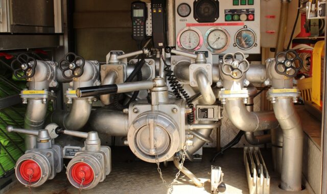
Central heating pump valves explained for hydronic heating systems
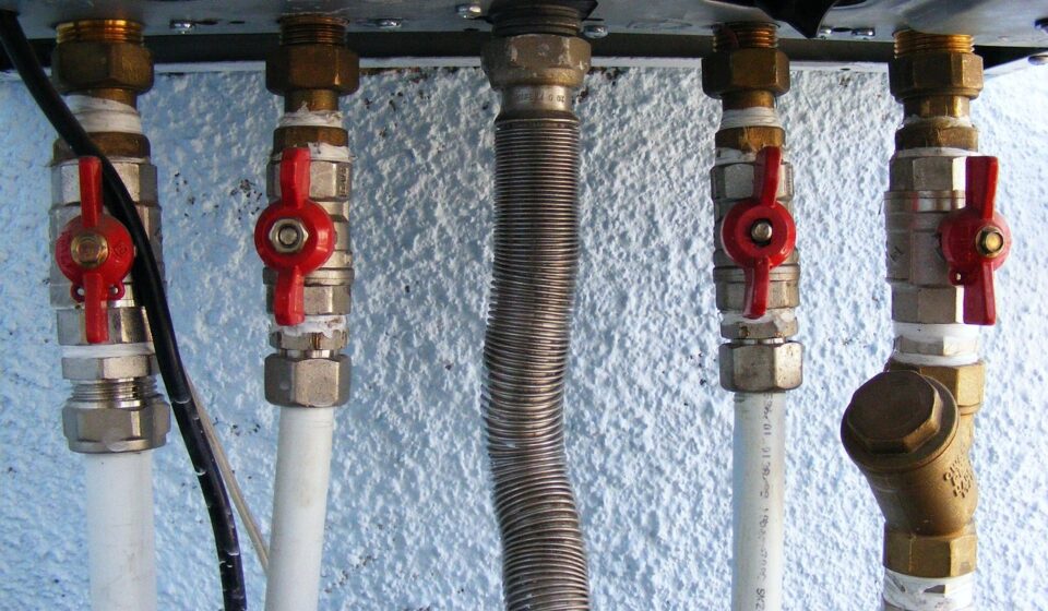
What central heating pump valves actually do
Central heating pump valves manage water flow around a wet, hydronic heating circulator and the pipework connected to it. In day-to-day maintenance, the term often refers to the two isolating valves fitted directly upstream and downstream of the pump. In system design, it can also cover check valves, bypass valves, balancing valves, motorized zone valves and radiator valves because each of these affects how the pump operates.
Their purpose is practical: isolate the pump safely for service, keep water moving in the intended direction, maintain enough flow for the boiler or heat source, limit unnecessary pressure loss and support stable room control. For equipment-focused readers, these components sit where pump selection and valve selection overlap in the wider Pumps and Valves category.

The main valve types used around a heating circulator
A central heating pump does not work on its own. It is part of a closed circuit that includes pipework, heat emitters, a boiler or heat interface unit, air separation, strainers, expansion equipment and controls. The table below separates the common valve functions so the term “pump valve” does not hide important design differences.
| Valve or device | Typical location | Main function | Common issue if wrong |
|---|---|---|---|
| Pump isolating valve | Immediately upstream and downstream of the circulator | Allows pump removal or servicing without draining the whole system | Seized stems, leakage at unions, or restricted bore causing poor flow |
| Check or non-return valve | On the pump discharge or in a branch circuit | Prevents reverse flow and unwanted circulation through inactive zones | Ghost heating, flow noise, or no flow if installed backwards |
| Automatic bypass valve | Between flow and return, often near the boiler or manifold | Opens when differential pressure rises as control valves close | Short-circuiting flow if set too low, or noisy valves if set too high |
| Balancing or commissioning valve | On branches, risers or terminal circuits | Sets design flow and helps distribute heat evenly | Hot nearby radiators and cold remote radiators |
| Motorized zone valve | On heating zones or domestic hot-water circuits | Opens only when that zone calls for heat | Pump running against closed circuits or zones warming unexpectedly |
| Thermostatic radiator valve | At individual radiators | Modulates flow according to room temperature | Changing system resistance, which can expose pump oversizing or poor bypass settings |
Public heating guidance such as UK Approved Document L, CIBSE AM14 and Hydraulic Institute pump life-cycle guidance all support the same engineering approach: pumps, valves and controls should be considered as one system, not selected as unrelated parts.
How valve selection affects pump performance
The pump creates the pressure difference needed to move water through the heating circuit. Every valve, bend, heat emitter and length of pipe adds resistance. If a valve has a small internal bore, is only partly open, or uses a restrictive pattern, the pump may be pushed to a less efficient point on its curve. The result can be higher electricity use, noise, uneven heating or premature component wear.
In a simple domestic central heating circuit, this may appear as one radiator taking much longer to warm than the others. In a commercial plantroom, the same hydraulic problem can show up as unstable flow through heat exchangers, excessive differential pressure at terminal units or poor return temperature control. The exact symptoms depend on the pump curve, pipe layout, emitter sizing and control strategy.
Variable-speed circulators can reduce some of these issues because they adapt to changing system resistance as thermostatic radiator valves or zone valves open and close. They do not remove the need for correct valve selection. A variable-speed pump still needs a reasonable system curve, clean strainers, correct valve orientation and commissioning that verifies actual flow. Hydraulic Institute life-cycle cost guidance is often summarized around this point: purchase cost is only one part of pumping economics; energy, maintenance and system reliability also matter.
Selection checklist for central heating pump valves
Choosing central heating pump valves should start with operating conditions, not thread size alone. These checks help avoid common mismatches.
- Connection size and pattern: Match the pump union, flange or threaded connection, but also confirm the valve bore. A full-bore isolating valve usually creates less pressure drop than a small-bore service valve of the same nominal size.
- Temperature and pressure rating: Use valves rated for the system’s maximum water temperature and pressure. Ratings should come from the valve manufacturer, not from visual similarity to another product.
- Flow direction: Check valves, some balancing valves and many pump bodies have direction arrows. A reversed valve can stop circulation or create noise that looks like a pump fault.
- Service access: The purpose of isolating valves is defeated if handles, union nuts or electrical terminal boxes cannot be reached after installation.
- Water quality: Dirty or magnetite-laden water can damage pump rotors, jam check valves and foul small valve passages. Strainers, filters and flushing procedures are part of the valve decision.
- Control strategy: Systems with many thermostatic radiator valves or zone valves may need differential pressure control, an automatic bypass or a pump mode suited to variable flow.
- Material compatibility: Brass, bronze, stainless steel and polymer components all have application limits. Compatibility with inhibitors, glycol mixtures and local water conditions should be checked.
For replacements, do not assume an old valve is correct just because it fits. Older pump isolating valves can seize open, leak when disturbed, or restrict flow after years of corrosion. If the pump is being replaced, the adjacent valves should be inspected at the same time.
Installation and commissioning points that prevent repeat faults
Most pump-and-valve faults are not exotic. They usually come from ordinary details missed during installation or commissioning. Manufacturer instructions commonly show isolating valves on both sides of the pump, accessible orientation, correct electrical isolation and attention to trapped air. The exact requirement depends on the pump model and local code, so the manufacturer’s document remains the controlling reference.
Before a pump is removed, the circuit may contain hot water, pressure and electrical hazards. In regulated heating work, isolation, draining, refilling and testing should be handled by a competent heating professional. After installation, the system should be filled slowly, vented, checked for leaks and operated through its control sequence. A valve left closed after servicing can produce a convincing but false “new pump failure.”
Commissioning should include more than confirming that the pump runs. Useful checks include verifying the pump direction arrow against system flow, opening both isolating valves fully, confirming zone valves travel correctly, setting balancing valves to the design intent, adjusting the bypass valve if present, and recording pump mode or speed. In larger systems, differential pressure and temperature readings across branches give a clearer picture than touch-testing pipes by hand.
Symptoms that point to valve-related problems
When a heating system performs poorly, the pump is often blamed first because it is visible and audible. Valve faults can create very similar symptoms. A structured diagnosis helps avoid unnecessary pump replacement. See also: Storage Systems.
| Symptom | Possible valve-related cause | Reason to check before replacing the pump |
|---|---|---|
| Pump runs but radiators stay cold | Closed isolating valve, stuck zone valve, airlock after valve work | The pump may be healthy but unable to move water through an open path |
| One zone warms when it should be off | Leaking zone valve or failed check valve | Reverse or gravity-assisted circulation can mimic control failure |
| Whistling or rushing noise at radiators | Excessive differential pressure as TRVs close | Pump setting, bypass setting and balancing may need correction together |
| Leak around pump unions | Worn gasket, overtightened union, corroded isolating valve face | Replacing only the pump head may not cure a valve-seat leak |
| Remote emitters heat slowly | Poor balancing or restrictive valves near the pump | Increasing pump speed can make nearby circuits noisier without solving distribution |
| Boiler short cycles after controls close | Insufficient minimum flow or bypass set incorrectly | The heat source may require a verified minimum flow path |
The practical lesson is to check valve position, valve condition and control sequence before reaching a conclusion about pump capacity. Many heating complaints are hydraulic distribution problems rather than simple component failures.
Maintenance practices for longer pump and valve life
Heating pump valves do not need constant attention, but they should not be ignored until a winter breakdown. During planned maintenance, isolating valves can be inspected for staining, mineral deposits or signs of seepage. Handles and stems should not be forced; a seized valve may need replacement rather than aggressive operation. Where access and controls allow, check valves and zone valves should be tested through their normal operating cycle.
Water quality is as important as mechanical condition. Suspended debris can score valve seats, block strainers and increase pump load. In systems where corrosion products are expected, cleaning, filtration and inhibitor maintenance can reduce repeat valve and pump problems. Any flushing or chemical treatment should follow the equipment manufacturer’s limits and local practice.
Documentation also matters. A simple record of pump model, pump mode, valve settings, bypass setting and commissioning observations helps future technicians distinguish an intentional setting from an accidental restriction. In commercial buildings, this record can reduce troubleshooting time after tenant changes, control upgrades or heat-source replacement.
Frequently asked questions
Are central heating pump valves the same as pump isolation valves?
Sometimes, but not always. In common maintenance language, central heating pump valves often mean the two isolation valves directly beside the circulator. In a wider system discussion, the phrase can also include check, bypass, balancing, zone and radiator valves that influence pump operation.
Should both sides of a heating pump have isolation valves?
In many hydronic systems, fitting isolation valves on both sides is standard good practice because it allows pump service without draining the whole circuit. The final arrangement should follow the pump manufacturer’s instructions, the system design and local regulatory requirements.
Can a faulty valve make a good pump look defective?
Yes. A closed isolating valve, jammed check valve, stuck zone valve or badly set balancing valve can prevent flow even when the pump motor is running. Diagnosis should confirm an open flow path before the pump is condemned.
Do variable-speed pumps remove the need for bypass or balancing valves?
No. Variable-speed pumps can reduce pressure and flow problems in variable-load systems, but they still depend on correct hydraulic design. Some systems still need balancing, minimum-flow protection or differential pressure control.
When should pump valves be replaced?
Replacement is usually considered when valves leak, seize, restrict flow, have damaged union faces, or no longer match the pressure, temperature or control needs of the system. Pump replacement is a good time to assess nearby valves because disturbing old fittings can expose hidden weaknesses.